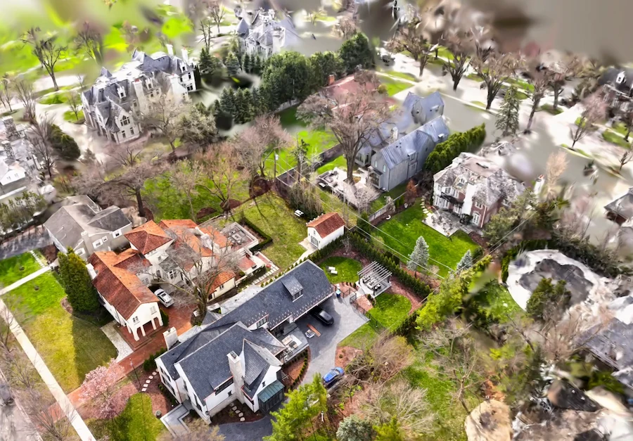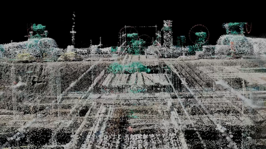
In the past, creating a 3D record of a factory floor required hiring a specialist, renting equipment, and waiting several days for results. Now, a facilities engineer can use a phone to scan the floor in the morning and have the data ready in their CAD tool by the afternoon. By allowing teams to complete scans in-house, companies can significantly reduce documentation costs and speed up project timelines, leading to faster decision-making and improved return on investment. This guide explains the entire process, from scanning a single production line to managing a multi-site digital twin program. It also covers safety when working near active machinery and how to export scans to plant CAD and BIM systems.
Which Method Fits Your Plant Documentation Need
Why Manufacturers Digitize Plants
The case for plant documentation has grown beyond simple record-keeping. There are four practical reasons facilities teams are scanning their floors today.
Digital twin foundation. A geometric scan of the plant is the starting point for any digital twin program. Services like Siemens Teamcenter, SAP Asset Intelligence Network, and Microsoft Azure Digital Twins all need a spatial model to anchor asset data to physical locations. Without an accurate as-built capture, those platforms are working from approximations.
Operations training. A navigable 3D model of the production environment lets new operators familiarize themselves with equipment layouts, emergency egress routes, and safety zones before entering onto the floor. This is particularly useful for facilities with complex MEP routing or confined-space work areas.
Equipment maintenance records. Scanning individual assets creates a geometric baseline for maintenance programs. When a pump, compressor, or conveyor system needs service, technicians can reference the scan to understand access routes, pipe connections, and clearances before arriving on the floor.
Insurance and compliance documentation. Many insurers and oversight agencies require documented evidence of equipment condition and facility layout. A timestamped 3D scan provides defensible documentation that a facility was in a specific configuration on a specific date.
What Needs to Be Captured
Before starting a scan program, it helps to be specific about what the deliverable actually needs. Different use cases require different levels of coverage.
Floor layout and spatial envelope. The overall dimensions of the building, column grid, wall locations, door and loading dock positions, and ceiling heights. This is the minimum for any facility documentation deliverable.
Equipment locations and footprints. The position, orientation, and physical extent of production machinery, conveyors, storage systems, and workstations. Critical for line-balancing exercises and factory layout planning.
MEP routing. Mechanical, electrical, and plumbing runs above and below the production floor. Overhead pipe racks, conduit runs, HVAC ductwork, and compressed air lines. Often, the hardest to capture because access is constrained and the geometry is complex.
Clearances and safety zones. Aisle widths, equipment exclusion zones, emergency egress corridors, and overhead clearances for forklift operations. These are frequently needed for compliance documentation and layout change approvals.
P&ID context. For process facilities, the physical routing of process piping must match the Piping and Instrumentation Diagrams. Scanning gives you the physical geometry; the P&ID gives you the system logic. The two need to reconcile before a facility model can support engineering workflows.
Workflow: Single Line, Single Building, Multi-Site
Starting with One Production Line
The fastest way to demonstrate value is to pick one production line and scan it end-to-end. A single line gives you a contained scope that can be completed in a morning, processed the same day, and presented to stakeholders before the end of the week.
Step 1: Define the line boundary. Identify the physical start and end of the line, including infeed and outfeed equipment. Note any overhead structures (conveyors, cable trays, lighting gantries) that are part of the line's spatial envelope.
Step 2: Scan the line in Space mode. Walk the length of the line at a steady pace, capturing both sides. You’ll want to slowly move your device up and down to capture high and low angles, base frames, floor-mounted conduit, and elevated structures. Capture from a position that gives the device a clear upward sightline.
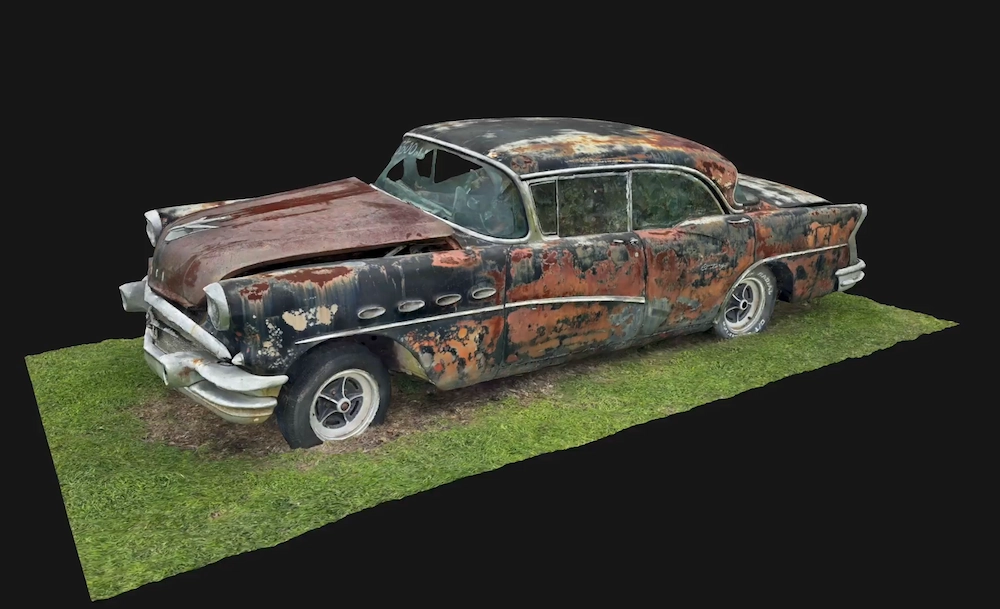
Step 3: Capture equipment details with Object mode. Key machines (presses, robots, CNC cells) benefit from a dedicated close-range capture using Polycam's Object mode, which produces high-quality photogrammetry or Gaussian splat outputs. This is more useful for maintenance records than a general Space mode sweep, as it captures fine geometry, access panels, and connection-point detail. In areas where visual reference matters, such as documenting control panel layouts or safety signage, the Walkthrough tool (available inside Space and Gaussian splat captures) overlays the original captured images onto the model.
Step 4: Export as LAS and review in CloudCompare. If you're exporting a Space or Photogrammetry capture, export the point cloud from Polycam as LAS, and load it into CloudCompare. Gaps around equipment bases or in overhead areas are easier to fix while you're still on site.
Scaling to a Single Building
Once the single-line pilot is complete and stakeholders have seen the output, scaling to the full building follows the same method with additional planning.
Divide the building into capture zones, typically aligned with production departments or fire compartments. Capture each zone as a separate session in Polycam, export each as LAS, and register the individual clouds into a single coordinate system using CloudCompare's ICP alignment tools.
For large buildings, plan for multiple capture days and assign capture zones to team members. Consistent overlap between adjacent zones (at least two to three meters of shared geometry) is what makes registration reliable.
Multi-Site Digital Twin Program
At the multi-site level, the technical workflow is the same, but governance becomes the dominant challenge. The section on multi-site governance below covers file naming, version control, and ownership. From a capture standpoint, the key is to establish a standard scanning protocol across all sites so that outputs are consistent enough to process and compare.
Tools like Autodesk Tandem and Siemens Teamcenter can ingest RCS/RCP point cloud data (via Autodesk ReCap) and structured BIM models derived from scan data. SAP Asset Intelligence Network can link asset records to scanned geometry once the spatial model is established. Polycam is the capture layer; these enterprise platforms are where the data lands.
Scanning Around Machinery Safely
Safety is not optional and not a footnote. Before any scanning activity on an active production floor, the following applies.
Lockout/tagout (LOTO) compliance. The OSHA standard for the Control of Hazardous Energy (29 CFR 1910.147) governs when and how energy sources must be isolated before employees perform work in proximity to machinery. Scanning near operating equipment is generally an observation task, not a maintenance task, and 29 CFR 1910.147 applies specifically to servicing and maintenance activities. That said, scanning in tight spaces around equipment with moving parts, pressurized systems, or live electrical panels requires a site-specific risk assessment before proceeding. Follow your facility's LOTO program requirements. If in doubt, stop the line.
PPE requirements. Wear the PPE required by the facility's standard operating procedures for the production area you are scanning. This usually includes safety boots, a high-visibility vest, a hard hat in areas with overhead operations, and hearing protection where required.
When to stop a line vs scan around it. For general floor layout and equipment footprint capture, scanning around an operating line is usually feasible with appropriate PPE and awareness of moving zones. For detailed close-range capture of individual machines, particularly around end-effectors, press zones, or robotic work envelopes, stopping or locking out the equipment before scanning is the right call. The point cloud will be cleaner anyway: moving parts during a scan introduce artifacts that complicate downstream processing.
Inform the floor supervisor. Before starting any scan session, brief the floor supervisor on your capture plan. They can identify hazards you haven't anticipated and arrange temporary line slowdowns or stoppages if needed.
Exports to Plant CAD and BIM
Once the point cloud is clean and registered, the next step is getting it into the engineering tools the plant team actually uses.
According to the Autodesk AutoCAD 2025 help documentation, point clouds derived from raw scan data must be converted to RCS or RCP files via Autodesk ReCap before attaching to an AutoCAD drawing. The same workflow applies to Plant 3D, which shares AutoCAD's point cloud handling infrastructure.
Multi-Site Governance
The technical challenge of multi-site scanning is manageable. The governance challenge is where programs stall.
Who owns the scans. Establish this before the first scan is taken. Is it facilities, engineering, IT, or the digital transformation team? Ownership determines who approves updates, who has access, and who is accountable when a scan is out of date.
Update frequency. A scan taken during a line reconfiguration is accurate for that configuration. After the next reconfiguration, it's a historical record. Decide upfront how often scans will be refreshed and tie that cadence to your change management process. Major equipment moves should trigger a rescan of the affected area.
File naming conventions. There is no industry-standard naming convention for scan files, but whatever structure you choose should capture site, location, date, and version at a minimum so files are identifiable without opening them. Establish and document the convention before the first scan is taken and apply it consistently across all sites.
Version control. Store point clouds in a location where previous versions are retained, not overwritten. A cloud storage system with versioning (SharePoint, Google Drive, or a dedicated asset management platform) provides a historical record useful for insurance claims, incident investigations, and change documentation.
Integration with enterprise asset management. For sites running SAP or IBM Maximo for maintenance management, the goal is to eventually link scan geometry to asset records so that a maintenance work order references the equipment's physical location in the model. This is a multi-step integration project, but it starts with having a clean, consistently named spatial dataset to integrate against.
FAQ
What are the best tools for manufacturing facility documentation? For speed, mobile phone scanning is the fastest way to document a facility without a specialist operator or equipment rental. Polycam exports directly to LAS, which is then imported into Autodesk Plant 3D, Revit MEP, and Navisworks via ReCap. For millimeter-accuracy survey work or large outdoor facilities, terrestrial scanners from Trimble or Leica Geosystems remain the professional benchmark.
How do I document a factory floor layout? The practical approach is to scan the floor in zones aligned with production departments, export each zone as LAS from Polycam, register the zones into a single coordinate system in CloudCompare, and export the combined cloud to ReCap for handoff to AutoCAD or Plant 3D. For a complete step-by-step guide, the single-building workflow above covers the full process.
What is the best way to create a digital twin of a factory? The spatial model is the foundation. Scan the facility to create a geometric record of the floor layout, equipment locations, and MEP routing. From there, platforms such as Siemens Teamcenter, SAP Asset Intelligence Network, and Microsoft Azure Digital Twins can layer in asset data, sensor feeds, and operational metrics. The ISO 23247 standard defines a reference architecture for manufacturing digital twins that describes how to organize physical elements, their digital representations, and the data connecting them.
What apps are best for scanning industrial equipment? For close-range documentation of individual machines, Polycam's Object mode produces high-quality photogrammetry or Gaussian splat captures of equipment frames, access panels, and connection points. Note that if you capture as a Gaussian splat, the exported physical model will use the photogrammetry output rather than the splat. For general floor layout and spatial envelope capture, Space mode is the right choice. The Walkthrough tool, available inside Space captures, overlays original images onto the model and is useful when visual reference of a space matters, such as for control panel layouts or safety signage. If a team just needs a quick visual lookaround without a point cloud or CAD deliverable, 360 mode is the fastest option. UpKeep and similar maintenance management platforms can link to scan outputs once the geometry is captured and processed.
How do I export a facility scan to CAD or BIM? Export from Polycam as LAS. Import the LAS file into Autodesk ReCap, which converts it to an RCS file (single scan) or RCP file (multiple scans). Attach the RCS/RCP to your AutoCAD Plant 3D, Revit MEP, or Navisworks project. From there, you can use the point cloud as a reference for drawing extraction, clash detection, or as-built verification. The Autodesk AutoCAD 2025 documentation confirms RCS and RCP as the supported point cloud formats for attaching to a drawing.
How often should a facility scan be updated? There is no single standard for scan update frequency. A practical approach is to tie rescanning to your change management process: any major equipment move, line reconfiguration, or new installation triggers a rescan of the affected area. Annual full-facility scans work well as a baseline refresh for facilities with moderate change rates. High-change environments (flexible manufacturing, frequent line changeovers) may benefit from quarterly captures of the most dynamic areas.