To scan a factory floor for an equipment install, capture one connected record of three things: the area the new machine will occupy, the route it travels to get there, and the services overhead above both. Scan the room around the machine as carefully as the machine, because in most retrofits the machine is not the constraint. Then register the captures, use the model as a fixed reference in CAD, and check fit by sectioning and measuring against it. One visit replaces the tape measure, the return trip, and the argument when the rigging crew arrives.
What the Survey Has to Answer
An install quote rests on six questions, and every one of them is a measurement:
- Can it get in? Door and dock clear widths, corridor turns, ramp gradients, what the route can carry.
- Does it fit? Footprint against columns, walls, adjacent machines, and the service envelope the vendor specifies.
- Can it be anchored? Slab condition, existing anchor stubs, embedded plates, pits, drains, and anything cut into the floor before.
- Do the services reach? Panel position, conduit runs, compressed air, coolant, exhaust, network.
- Does anything overhead block it? Duct, tray, sprinkler, crane rails, structure, and the rigging height above the machine.
- Does the floor still work afterwards? Aisle width for vehicles and people, the egress route, the paths operators take.
| What you capture | The detail that matters | What it decides |
|---|---|---|
| Machine envelope | The existing unit and its plinth, including guards, control cabinets, and the full travel of anything that moves | The starting point for the new design, and the clearance to everything fixed |
| Foundations and anchor points | Anchor positions and bolt spacing, grout pads, embedded plates, cracks, patches, earlier repairs | Whether the new machine reuses the old anchors or needs a new foundation |
| Floor condition | Saw-cut joints, slopes to drains, patches, cut-and-pour repairs, pits and trench drains | Where levelling grout is needed, and where the slab has already been opened up |
| Overhead services | Duct, conduit, cable tray, sprinkler branch lines, air mains, crane rails, high-level lighting | Machine height, the rigging path, and which service has to be relocated |
| Aisles and marked zones | Width between fixed objects, painted pedestrian and vehicle lanes, hatched zones | Whether the line can still be loaded, serviced, and evacuated |
| Route in | Dock or door openings, corridor width, turns, ramps, lift capacity | Whether it arrives in one piece or has to be split |
Documenting several bays is the same job at a larger scale, and the plant documentation guide covers zoning and registration.
Step 1: Scan the Envelope, the Aisle, and the Route In
Start at the edge of the job, not at the machine. The machine is easy to photograph and rarely the surprise; the room around it is where designs fall apart three weeks later.
Walk the perimeter twice, once at chest height and once low along the floor line. The low pass is the one people skip: floor-mounted conduit, anchor stubs, pit edges, and drain grates all sit below a normal sightline.
Then a raised pass over the install footprint. Overhead detail thins out with distance from a phone, so walk under the area in two directions rather than catching it from one end of the bay. If a duct runs over the machine's position, scan it from underneath and from both sides.
Take the aisle, the forklift route, and the install corridor in the same session where the space is continuous. Where it is not, capture separate zones overlapping by two or three metres, because shared geometry is what lets you register them later.
At every door, scan the opening from both sides and run a tape across the clear width and height anyway. The mesh gives a dimension; the rigger wants the clear opening, not the frame.
Don't tidy the floor first. Pallets and a parked forklift are clutter you can crop, and they show how the bay really runs. Capture the painted markings too: yellow lines and hatched zones encode rules the plant enforces, and a layout that deletes a walking route gets rejected at the first walk-round.
Work to the plant's rules: area PPE, a briefing with the floor supervisor, no stepping through a light curtain for an angle. If the detail you need sits behind a guard, stop. Removing a guard is servicing work, and the OSHA control of hazardous energy standard covers it. Follow the lockout procedure or flag it as unmodelled.
Step 2: Capture the Machine Itself
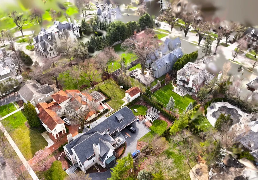
The room capture answers where things are; the machine capture answers what shape they are. For the room, Space mode is right. It holds position across a bay, gives you a navigable model and a floor plan, and puts the machine in context with columns and aisles. What it will not do is resolve a mounting face at close range.
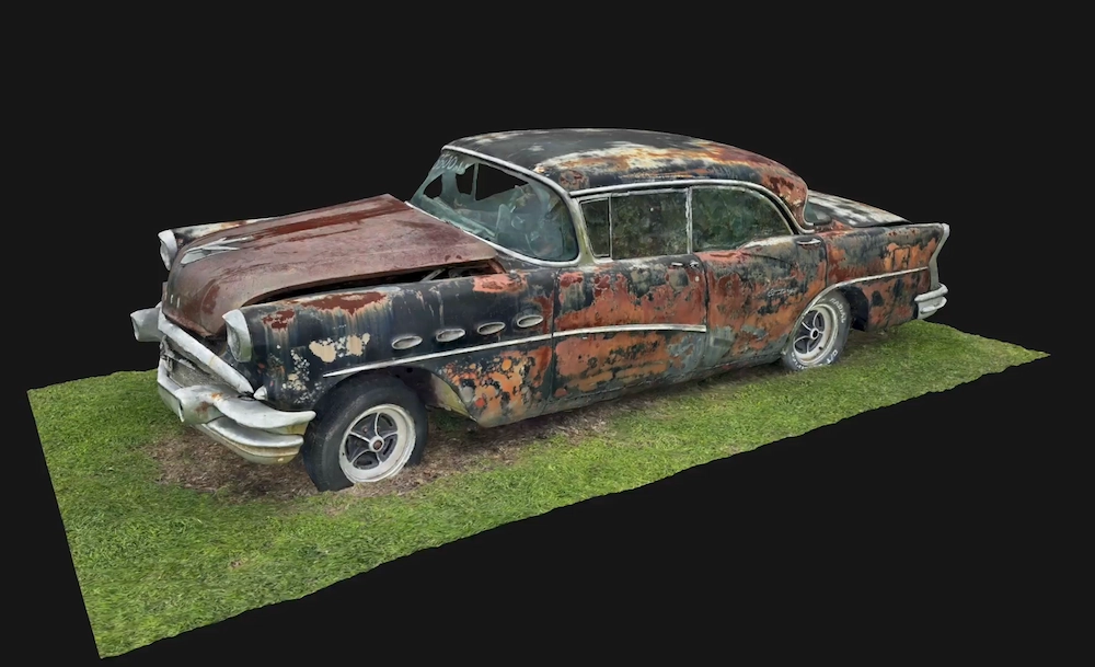
For the machine, use Object mode and walk a full circle, raising and lowering the phone, keeping half of each frame overlapping the last, walking slightly past the start to close the loop. Where one part occludes another, get the phone into the gap rather than trusting the software to invent it. An Object capture carries its own coordinate space, so place it inside the room scan rather than assuming it knows where it sits.
The reason to bother is the connection points. On a machine that has stood on the floor for fifteen years, the new unit has to mate to what is actually there, not to what the drawing says. Object mode captures mounting faces, shaft ends, ports, and flanges at a detail the room scan cannot reach. The mechanical parts guide covers overlap and lighting.
Two things cost you a rescan. Motion: capture a running machine and you capture a blur. Surface: polished stainless, black frames, and wet floors are where photogrammetry loses geometry. Add diffuse light, shoot more angles, and never design a mounting face off a bridge the mesh invented.
Nameplates get their own pass. The Walkthrough tool inside a Space or splat capture overlays the original photos where you took them, which is how you read a model number or voltage rating off a plate too small for the mesh. Photograph every plate too; that habit prevents more return visits than anything else here.
Step 3: Register the Scans and Set a Datum
With more than one zone, register them into one coordinate system before anyone designs on them. CloudCompare's alignment tools will do it; the requirement is overlap, two or three metres of shared capture, or the registration is guesswork.
Then pick a datum and write it down: a column face, a wall, or a grid intersection, with one axis down the aisle. Every section afterwards refers to that origin, so nobody argues about which end of the bay was measured from.
Check the scale before trusting any number off the model. Mesh formats often carry no units, and the Fusion 360 and SolidWorks walkthroughs both show a capture arriving a factor out and being scaled by hand. Measure something known: a door leaf, the column spacing, a machine that still has its drawing.
Step 4: Check Fit and Clashes in CAD
Import the scan as a reference body, not a solid: the new assembly is modelled as solids beside it, and the scan stays a record of the room as found. Sections do more work than orbiting. Cut one at the anchor plane, one at mid-machine, one at the operator clearance plane, one at the lowest overhead service. Clashes show up in a section long before anyone notices them in a 3D view.
Measure to the right surface. What matters is clearance to the nearest fixed object at the widest point of the machine, guards and hinged doors included. A fit checked against a nominal footprint is checked against a number from a catalogue.
Check the service envelope, not just the running one: panels that hinge, drawers that pull, a hook that has to reach a lifting eye, a technician who has to stand somewhere. Vendor drawings state those clearances; the scan says whether the room has the space.
Check the install path separately. Model the machine as a box and move it along the captured corridor and through the doors. Retrofit problems are less often about fitting in the room than getting through the opening.
Overhead is where the surprise sits. Compare the lowest obstruction over the footprint with the top of the machine plus rigging. A sprinkler line that has to move is a contractor, a permit revision, and a week.
Be precise about what is doing the checking. Polycam captures and exports geometry; it does not run clash detection, tolerance analysis, or structural checks. The check is a manual review in your CAD tool: a section, a measurement, an interference check against the captured model. A formal multi-discipline report needs a federated model in Navisworks or similar, with the scan as one input.
Step 5: Export to the Team's CAD Tools
Ask the mechanical team what they open it in before you export; the answer changes the format.
- Fusion 360 takes OBJ or STL, inserted as a mesh, with a scale check before it becomes reference or a solid body. The Fusion 360 workflow covers the rest.
- SolidWorks takes STL or OBJ, arriving as a graphics body that converts to a mesh body. The format guide says which.
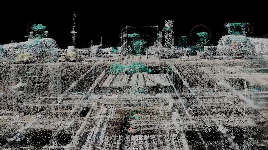
- AutoCAD, Plant 3D, Revit, Navisworks take a point cloud: export LAS, convert to RCS or RCP through ReCap, attach as reference. Geometry is read off by section.
- CloudCompare, MeshLab take LAS or PLY for registration, cropping, and measurement.
- DXF is the plan-view option for layouts and for anyone who will not open a 3D tool. A shared link covers everyone else.
Send the datum, the scale correction, and the capture date with the file. A scan without a stated origin is a picture; with one it is a reference four people can measure from without disagreeing.
What the Scan Cannot Tell You
A scan trusted too far is worse than no scan.
- Load ratings. A mesh shows the top of the slab, not its thickness, reinforcement, or post-tensioning. Point loads and anchor pull-out are structural questions for an engineer.
- Hidden services. Conduit in the slab, pipe in the wall, rebar, buried duct: invisible to a camera and to LiDAR. Ground-penetrating radar or current plant drawings is the tool, and neither is a scan.
- Electrical capacity. You can capture the panel, its label, and its position, not the spare breaker spaces or available capacity inside it.
- Tolerances. A phone capture is an approximation, not a certified measurement. Polycam publishes around half an inch on standard interior captures. Millimetre-level alignment to an existing line takes a total station or a laser tracker.
- Behaviour. Deflection, vibration, thermal growth, and settlement are things a static capture cannot hold.
- Code compliance. You can measure an aisle. Whether it satisfies the adopted code for egress width, sprinkler obstruction, or area classification is for the authority having jurisdiction.
When to call an engineer: before cutting or core-drilling a slab, removing a column or wall, adding a mezzanine or crane, changing a sprinkler layout, or committing a machine's point loads to a floor nobody has checked. Most installs also need a permit, and a permit needs drawings someone can stamp. The scan makes that engineer's site visit shorter and their assumptions better. It does not replace the visit or the stamp.
FAQ
How do I scan a factory floor for an equipment install?
Capture the bay the machine will occupy, the aisle and forklift route it has to travel, and the overhead services above both. Use Space mode for position across the floor, Object mode for close detail on the existing machine, then register the captures and section them in CAD to check fit.
Can Polycam detect clashes for me?
No. Polycam captures and exports geometry. The clash check is a manual review in your CAD tool, sectioning and measuring the new design against the captured model. A formal multi-discipline clash report needs a federated model in software built for it.
Do I need to scan the whole plant or just the bay?
Just the bay, plus the route in and out, is enough for a single install. Scan wider when the new machine shares services, crane coverage, or aisles with neighbouring lines, since those are the constraints a bay-only scan misses.
What accuracy should I expect from a phone scan of a machine?
Polycam publishes around half an inch on standard interior captures, which is enough for layout, clearance, and CAD reference work. It is not a substitute for a total station or laser tracker where a new unit has to align to an existing line within a millimetre.
How do I get the scan into SolidWorks or Fusion 360?
Export OBJ or STL and insert it as a mesh. Neither format reliably carries units, so measure a known feature and scale before you trust a dimension. Both tools can convert the mesh to a solid body if the scan quality allows.
Can a scan tell me if the floor will take the machine's weight?
No. It records the floor surface, not the slab thickness, reinforcement, or its condition underneath. Point loads and anchor pull-out need drawings, core samples, or a structural engineer's assessment.