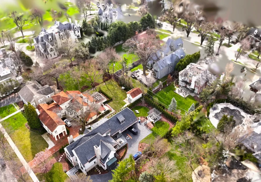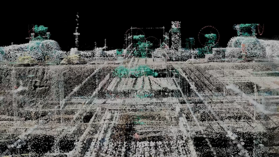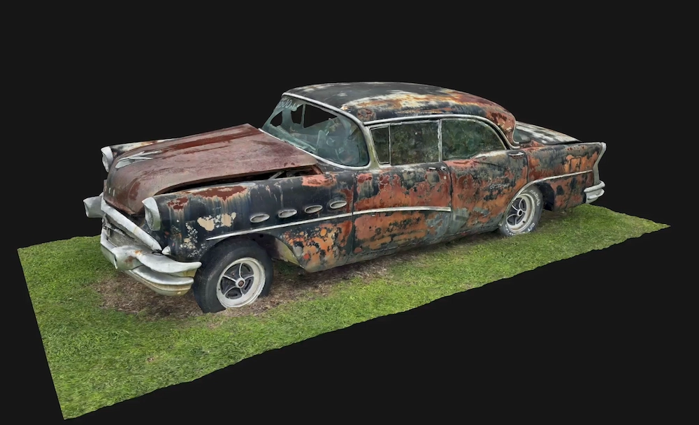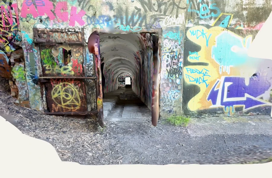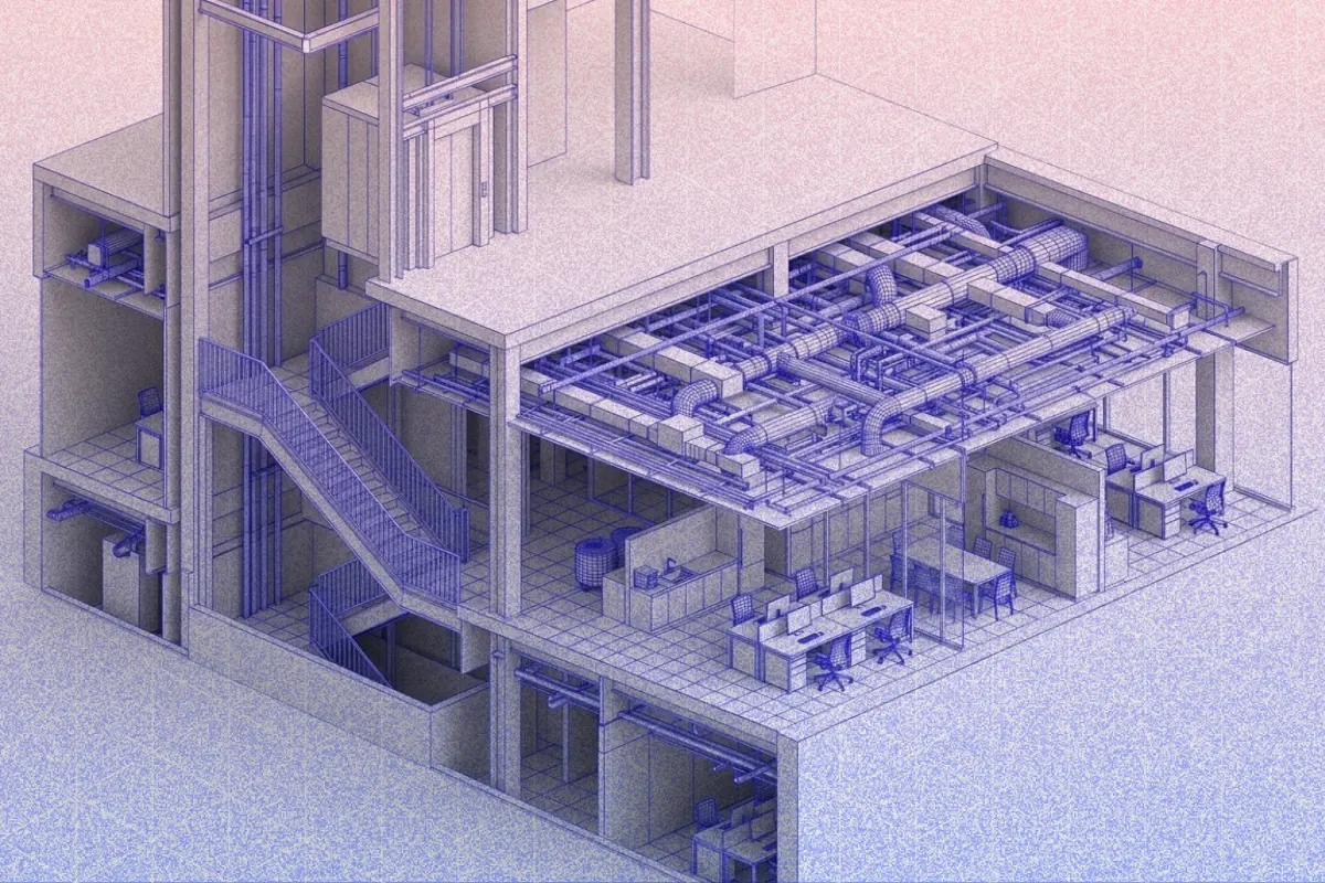
If you finish a scan session without a deliverable, all you have is raw data. This guide explains how to turn a Polycam capture into a floor plan, a DXF file, or a point cloud ready for BIM modeling. It also includes tips for capturing MEP and a checklist for handing off to clients.
Three Deliverables From One Capture
What "As-Built" Actually Means
The term gets used loosely on most projects. The formal definition comes from AIA Document B101, which calls them "as-constructed record drawings" and describes them as the record of the project as constructed, based on information the contractor provides to the owner. AIA's own guidance notes that, because as-constructed record drawings are based on the contractor's field markups, the architect is not responsible for their accuracy or completeness.
In everyday practice, as-builts cover three distinct things that often get conflated:
As-constructed record drawings document what was built during a construction project, typically marked up from the construction documents by the contractor and submitted at project closeout.
Record drawings are the architect's version: the original construction documents updated to reflect all changes, addenda, and field modifications. According to the AIA, these are a supplemental service under B101 and not automatically included in basic services.
Existing conditions drawings document the current state of a building that predates the project. This is the most common use case for 3D scanning: you're measuring what's there, not what was designed or built. NCARB's own Competency Standard for Architects lists evaluating existing project conditions as one of the core competencies expected of a newly licensed architect, which is a good indicator of how central this work is to everyday practice, not a niche skill.
This guide primarily covers documenting existing conditions, which is what most retrofit teams, AEC firms, and facilities managers mean by "as-built" drawings.
Scanning Workflow for As-Built Accuracy
Good drawings start with good scans. These steps work whether you are scanning one room or an entire building.
Step 1: Walk the space before scanning. Before opening Polycam, walk through every space you need to document. Identify rooms that will be hard to capture (narrow corridors, dark basements, plant rooms with dense equipment), features that are easy to miss (stair landings, mezzanines, external plant areas), and any areas where access will be limited during the scan session. Sketch a rough zone plan if the building has more than four or five rooms.
Step 2: Set up Space mode and start capture. Open Polycam and select Space mode. Walk through each room at a steady pace, keeping the device facing walls and surfaces rather than sweeping through the air. For rooms where ceiling height matters to the deliverable, physically raise the device as you go to capture the ceiling plane in the same pass, rather than tilting the phone at a fixed height or coming back through a second time.
Step 3: Overlap adjacent captures at doorways and junctions. The most common cause of misregistration in a scan is insufficient overlap at doorways and junctions. As you move from room to room, slow down at the threshold and make sure the scan has captured geometry on both sides of the opening before moving on.
Step 4: Deliberately capture structural elements. Columns, beams, and load-bearing walls are the skeleton of any as-built drawing. Don't assume a general room sweep has caught them by accident. As you move through the space, slow down and pay deliberate attention to any structural element that will appear in the drawing, rather than planning a separate pass to go back for it.
Step 5: Check the mesh preview before leaving the site. Review the on-device mesh preview against your zone plan. Check for gaps at room corners, thin coverage along walls that were captured at a distance, and missing areas. Re-scan anything that looks thin before leaving.
Capturing MEP for As-Built Documentation
MEP is where most as-built captures fall short. Overhead services are easy to miss in a general room sweep, and they're among the most important elements for retrofit and coordination work.
Step 1: Identify which services matter to the deliverable. Not every pipe run needs to be documented at the same level of detail. Before scanning, confirm with the project team which services are in scope: supply- and return-air ductwork, chilled-water and heating pipework, electrical conduit and cable tray, sprinkler mains, and drainage runs. Document this in your zone plan so nothing gets missed.
Step 2: Scan ceiling-level services in the same pass. During the general room sweep, raise the device toward the ceiling more frequently in areas with visible overhead services, capturing duct runs, pipe racks, and conduit routes on the same pass rather than a separate one. Keep the device moving steadily; holding it still in one position tends to produce artifacts rather than useful geometry.
Step 3: Capture mechanical rooms from multiple angles. Mechanical rooms have dense, complex geometry. Rather than making multiple passes, move slowly through the space in a single session, rotating the device to cover head height, low angles, and overhead services as you go. Check the mesh preview before leaving the room and re-scan only if there are obvious gaps.
Step 4: Document exposed pipe and duct runs in corridors. Corridors with exposed services are common in industrial, healthcare, and education buildings. Capture these by raising the device toward the ceiling as you walk the length of the corridor, moving slowly enough in that single pass to give the sensor a clear look at dense, low-ceiling service runs rather than planning to come back through a second time.
Step 5: Note what couldn't be captured. Some services will be inside ceiling voids, within duct casings, or otherwise inaccessible. Note these explicitly in your handoff documentation so the drawing team doesn't try to infer what's there. An honest gap note is more useful than a guess.
To document equipment or fixtures with complex geometry, use a hybrid approach. First, capture the entire space in Space mode. Then, switch to Object mode for a close-up photogrammetry scan of the specific item. Space mode provides the overall spatial reference, while Object mode captures fine surface detail. This combination ensures you get both context and the detail needed for elements that require more than just a general scan.
Terrestrial scanners like the Leica BLK360 or FARO Focus produce much denser point clouds at ceiling level from a single tripod setup, making them better for capturing complex, multi-layer service zones. If your main goal is MEP coordination in densely serviced areas, investing in a terrestrial scan pays off. For single-layer exposed services in renovation or retrofit projects, Polycam's Space mode provides enough detail for reference documentation.
From Scan to 2D Floor Plan
Polycam generates a 2D floor plan automatically from a Space mode capture. The floor plan is derived from the scan geometry at a default cut plane.
Step 1: Open the capture and select Floorplan view. After processing, navigate to the floor plan view in Polycam. The generated plan shows walls, openings, and room boundaries derived from the scan geometry.
Step 2: Review the floor plan against the space. Check the generated plan against your site notes and photos. Common issues include:
- Walls that appear thin or broken where coverage was poor
- Openings that are missing because the door was closed during capture
- Room boundaries that don't close cleanly at complex junctions
Step 3: Export the floor plan. Polycam exports the floor plan as a DXF file or as an image. For simple documentation (client reference, space planning), exporting images is often sufficient. For CAD use, export as DXF.
Polycam's floor plan works well for space planning, leasing documents, simple room schedules, and as a quick reference for facilities management teams.
Polycam's floor plan is not enough when you need to add dimensions by hand, when room boundaries are complex or curved, or when the drawing must meet standards for permits or professional approval. In these cases, use the DXF export as a starting point and finish the drawing in CAD.
From Scan to DXF Handoff
The DXF export from Polycam is the starting point for a CAD as-built drawing. AutoCAD is the standard tool for this step; the process is the same in BricsCAD or any other DXF-compatible application.
Step 1: Export DXF from Polycam. Tap the download icon (the downward-facing arrow) on mobile, or click download on the web, and select DXF as the format. The export includes the floor plan geometry as 2D line work.
Step 2: Open in AutoCAD and check units. Open the DXF in AutoCAD. The first thing to check is the drawing units. Go to Format > Units and confirm the unit matches your project (meters or feet). If the drawing is at an unexpected scale, set the correct units and use SCALE to correct it.
Step 3: Clean up the line work. The imported line work will need cleanup before it's a usable drawing:
- Join broken wall lines using PEDIT or JOIN
- Remove duplicate lines and artifacts
- Close wall corners that didn't register cleanly
- Add or correct door and window openings that the scan missed
Step 4: Add dimensions, annotations, and a title block. Once the geometry is clean, add dimensions, room labels, a north point, a scale bar, and a title block per your firm's drawing standards. AIA's own quality-control guidance for working drawings emphasizes that construction documents are the primary way clients judge an architect's services, and that drawings should be free of conflicts between drawings and specifications and coordinated across the set.
Step 5: Publish and check. Plot a check print and review it against your site photos and notes. Check all dimensions for plausibility and confirm any critical measurements against your laser distance meter notes from the site.
From Scan to Revit and BIM Model
When the deliverable is a BIM model rather than a 2D drawing, the scan becomes a reference for a Revit modeler rather than a direct drawing source.
Step 1: Export LAS from Polycam. Export the point cloud as LAS from Polycam. LAS is the format Autodesk ReCap expects, and it's the cleanest path into Revit.
Step 2: Import LAS into Autodesk ReCap. Open ReCap, import the LAS file, and let ReCap index it into an RCS file.
Step 3: Link the RCS into Revit. In Revit, go to Insert > Point Cloud and link the RCS file. The point cloud appears as a reference in all views.
Step 4: Model from the point cloud reference. The Revit modeler places walls, floors, doors, and building elements using the point cloud as a geometric reference. This step is the BIM modeling work itself; the quality of the output depends on the modeler's judgment and the LOD target agreed at the start of the project.
QA/QC Before Client Delivery
A drawing or model that leaves the office with an error is harder to fix than one that gets caught before it's sent. The checks that matter depend on which deliverable you're producing.
For a 2D floor plan or DXF drawing set:
- Cross-reference every drawing against site photos. Each room should have a reference photo. Check that walls, openings, columns, and services shown in the drawing match what the photos show.
- Check closure of all room outlines. Every room boundary should close. Open wall lines are a common artifact of the DXF export and need to be corrected before delivery.
- Verify critical dimensions with a laser distance meter. For any dimension that drives a design decision (structural bay width, clear opening for an accessible route, equipment clearance), check it against a laser distance-meter reading taken on site. Polycam's ±½ inch accuracy on standard interior captures is sufficient for most documentation work, but critical dimensions warrant a manual check.
- Check layer organization and file cleanliness. Confirm all line work is on the correct layers, all annotation is on the annotation layer, and no geometry is on layer 0. A clean file is easier for the client or consultant to work with.
- Confirm units one more time. A drawing that looks right on screen but was never confirmed against Format > Units can still be off by a factor of ten or a unit system. Check it again immediately before publishing, not just when you first opened the DXF.
For a point cloud or BIM handoff:
- Open the LAS file to confirm it isn't corrupted. Load it in CloudCompare or ReCap and confirm it opens cleanly and the coordinate system is what you expect, local or georeferenced.
- Spot-check the RCS/RCP file in Revit before handing it off. Link it into a test view and confirm the point cloud appears where expected relative to any existing project geometry.
- Note known coverage gaps for the modeler. If any areas were thin, inaccessible, or didn't scan cleanly, flag them explicitly rather than letting the modeler discover it mid-modeling. A flagged uncertainty is more useful downstream than a confident element that turns out to be wrong.
For any deliverable: plot or export a check version and review it against your site notes and photos one more time before it goes out. Catching a gap or a wrong dimension at this stage costs minutes; catching it after delivery costs a client conversation and possibly a return site visit.
Client Handoff Package
A full as-built handoff is more than just the drawings. The best packages include:
Drawings. The final DXF or PDF drawing set, at the agreed scale and in the agreed format. If the client uses Bluebeam or Procore for document management, confirm the preferred file format before delivery.
Point cloud file. The LAS export from Polycam, with a note on the coordinate system and units. Even if the client only asked for drawings, having the point cloud available means any disputed dimension can be checked without a return site visit.
Site photos. A selection of reference photos from the site visit covering each major space and any areas of complexity or uncertainty. These are the first things a modeler or reviewer reaches for when something looks wrong in the drawings.
Polycam scan link. If the client has Polycam access, sharing the scan link lets them navigate the 3D model directly. This is particularly useful for clients doing space planning who may want to take additional measurements after delivery.
Change log. If you are updating an existing drawing set, add a short note about what changed—such as rooms added, services documented, or dimensions corrected. This is a basic part of document control, but it often gets missed.
Common Mistakes in As-Built Documentation
- Scanning too quickly. If you move too fast, you will get thin coverage and broken wall lines. Take your time and scan slowly for better results.
- Missing overlap between rooms. Doorways are where scans connect one room to another. If you rush through doorways, you are more likely to end up with rooms that don't line up correctly.
- Not capturing ceiling height. A floor plan without confirmed ceiling heights is incomplete for most as-built deliverables. Add an upward pass in every room.
- Skipping MEP. Overhead services are easy to miss and difficult to add later. If MEP is part of your project, plan special scans for it instead of relying on a general sweep.
- Wrong units in AutoCAD. DXF files can open at the wrong scale if you don't check the units first. Always confirm the units before you start working on the drawing.
- Not noting scan limitations in the handoff. List any areas you couldn't scan, surfaces that didn't come out well, and any extra measurements you took with a laser meter. It's easier to manage a client who knows about gaps up front than one who finds out later.
- Missing rooms or spaces. Check your zone plan before leaving the site. A missed room is a common and entirely avoidable error.
FAQ
How do you create accurate as-built drawings from site measurements? To quickly document existing conditions, capture the space in Polycam's Space mode, export the floor plan as DXF, clean up the line work in AutoCAD, and add dimensions, annotations, and a title block. For BIM, export the LAS file from Polycam, convert it to RCS in Autodesk ReCap, link it into Revit, and model using the point cloud as a reference. Output accuracy depends on how well you capture the site; refer to the scanning workflow section for tips.
What is the best workflow for as-built documentation? For most retrofit and renovation projects, the practical workflow is: Space mode capture in Polycam, mesh preview quality check before leaving the site, DXF export for 2D drawing work or LAS export for BIM, cleanup in AutoCAD or Revit, and a client handoff package including the drawings, point cloud, and site photos. This covers most LOD 200-300 documentation needs. For projects requiring LOD 350 or higher, supplement with a laser distance meter for critical dimensions, or commission a terrestrial scanner.
What should a complete as-built drawing set include? At minimum: dimensioned floor plans at an appropriate scale, reflected ceiling plans if services are in scope, key elevations or sections for spaces with significant height variation, a title block with project name, date, scale, and author, and a north point and scale bar. For MEP documentation, add service routing diagrams or annotated RCPs. For project closeout submissions to clients using Bluebeam or Procore, confirm the preferred format and naming convention before delivering.
What are the best tips for capturing MEP in as-built documentation? Plan MEP capture before arriving on site: know which services are in scope and where they run. Scan ceiling-level services with dedicated upward-angled passes rather than relying on the general room sweep. Give mechanical rooms extra time; they reward a slow, deliberate single pass covering multiple angles. Note anything that couldn't be captured in the handoff documentation (services inside voids, inaccessible risers).
How do as-built drawings differ from record drawings and BIM models? As-built drawings (formally "as-constructed record drawings" per AIA B101) document what was built during construction, based on contractor field markups. Record drawings are the architect's version: the original construction documents updated to reflect all changes. Existing conditions drawings document the current state of a building, which is what 3D scanning typically produces. A BIM model is a structured, object-based representation of building elements, built using the scan as a reference rather than directly from it.
What file format should I use for an as-built handoff? For 2D drawing handoffs, DXF is the most compatible format across CAD applications. PDF is appropriate for client review and document management platforms like Bluebeam or Procore. For BIM handoffs, the point cloud is delivered as LAS (converted to RCS/RCP in Autodesk ReCap for Revit)