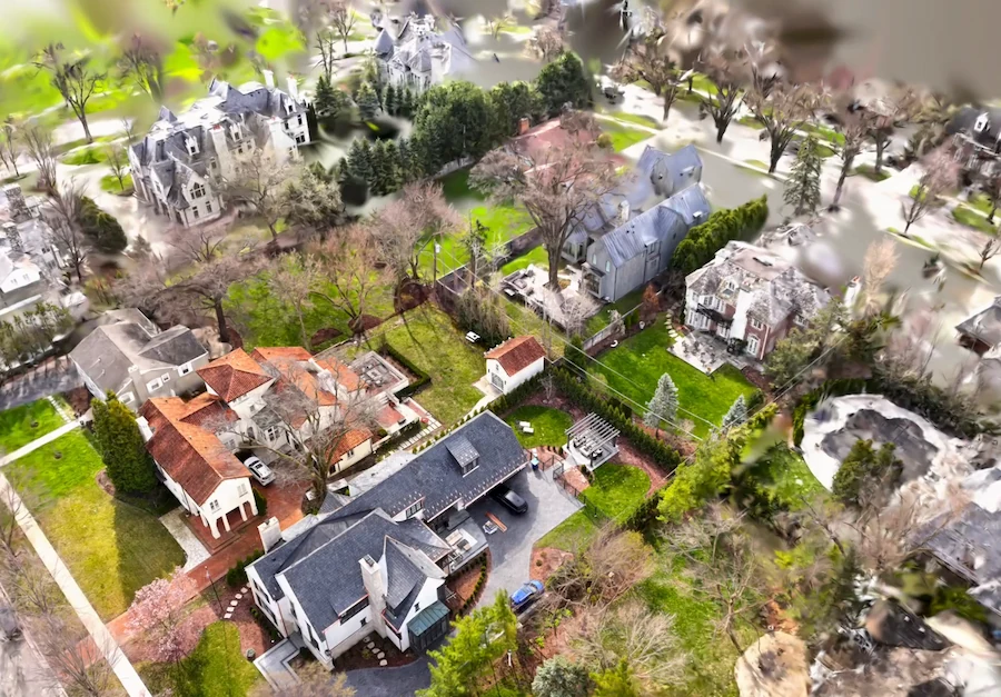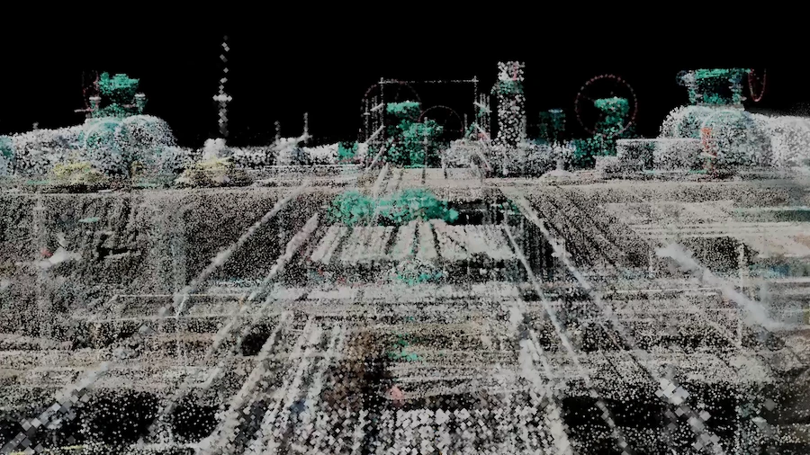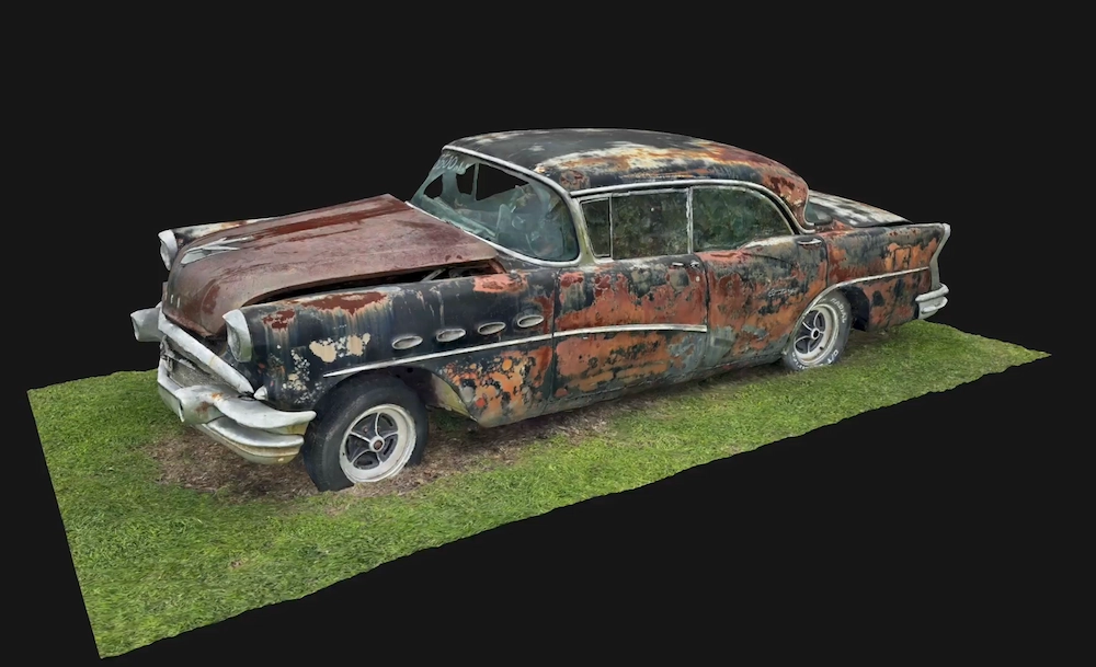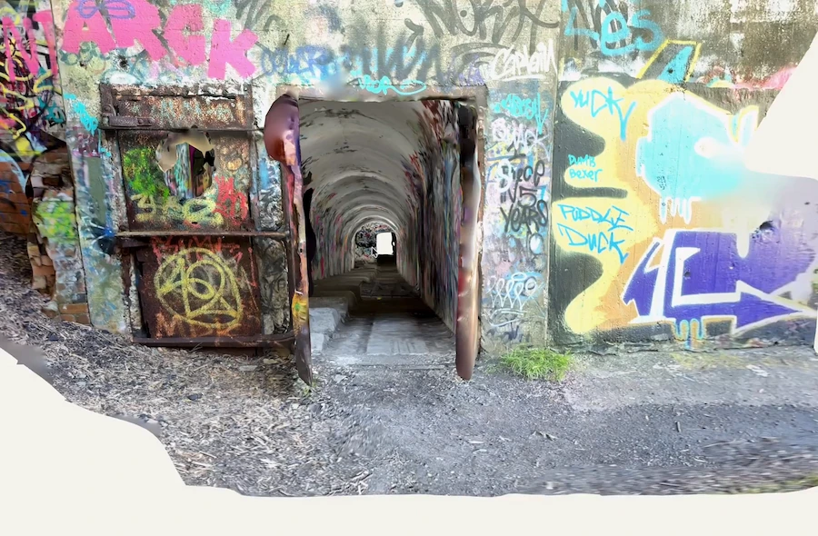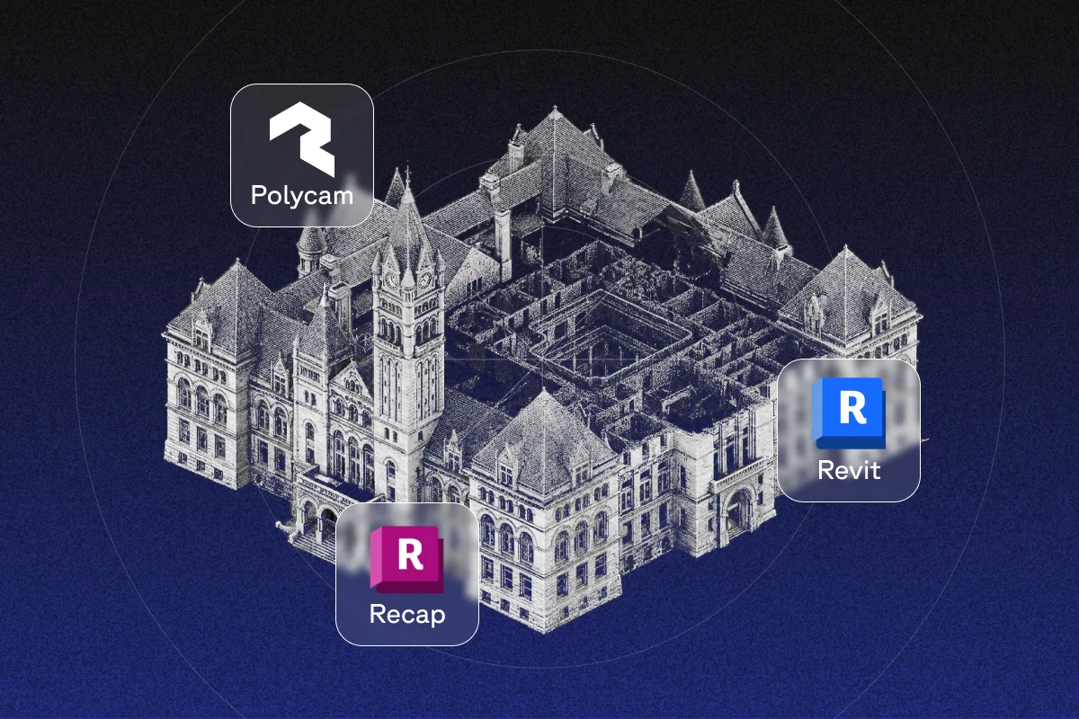
Many scan-to-BIM discussions focus on the wrong issue. Instead of asking which scanner to use, it's more important to decide what LOD the project really needs. Using a phone for capture and converting it with Autodesk ReCap into a Revit-ready point cloud is enough for LOD 200 and most LOD 300 work, and it saves both time and money compared to a terrestrial scanner. For LOD 350, LOD 400, and fabrication-level tasks, a Leica BLK360 or FARO Focus is the better choice. It's more helpful for a BIM team to be clear about these limits than to assume mobile scanning can handle everything.
Which Capture Method Fits Which LOD
What Scan to BIM Actually Means
Scan-to-BIM is the process of capturing a building's existing conditions with a scanner and using that spatial data as a reference to build an intelligent, object-based BIM model. The scan is not the model; it's the evidence the modeler works from.
The LOD framework sets the level of detail expected in the model. BIMForum’s LOD Specification (2025 edition) explains and standardizes how much detail each model element should have, rather than the model as a whole.
Accuracy Tiers: What Each Capture Method Actually Delivers
Polycam standard accuracy of ±½ inch on standard interior captures for Space mode, measured against a professional laser distometer. In practice, mobile captures suit LOD 200 and most LOD 300 work; terrestrial scanners are better suited to LOD 350 and above, where tight tolerances are needed for coordination or fabrication.
Compared to the Leica BLK360 (G1): The BLK360 (G1) delivers 6mm accuracy at 10m and 8mm at 20m from a fixed tripod position. It produces very high point density at each position, making it reliable for MEP coordination at LOD 300-350. It requires a tripod, multiple scan positions spaced roughly 25 to 30 feet apart, and processing in Cyclone REGISTER 360 PLUS afterward. Polycam's walk-through capture is faster to execute but captures less point density per square meter. Leica's newer BLK360 G2 and the entry-level BLK360 SE have different speed and accuracy specs than the original G1.
Compared to FARO Focus Premium: The Focus Premium offers up to 2mm accuracy and is built for fabrication-level tasks. For LOD 400 structural steel, MEP fabrication, or prefabrication, the FARO Focus is the right choice. For retrofit planning and as-built documentation at LOD 200-300, using a FARO Focus usually isn’t worth the extra time and cost.
Phone-Based Capture Workflow with Polycam
Step 1: Set the LOD target before you begin. Check with the BIM team to confirm the LOD target before you go to the site. You can capture LOD 200 and most LOD 300 work in Space mode. If some elements need LOD 350 or LOD 400, list them separately and plan to use a terrestrial scanner or take extra measurements for those spots.
Step 2: Capture using Space mode. Walk through each area at a steady pace, keeping your device pointed at the walls and surfaces. In spaces important for MEP, such as plant rooms or ceiling voids, make sure to angle the device upward to catch overhead services in a single careful pass.
For more details on MEP capture, check Polycam’s As-Built Drawings guide.
Step 3: Check mesh coverage before leaving the site. Review the on-device mesh preview against your zone plan. Re-scan any areas with obvious gaps or wall doubling before leaving. A gap found on-site takes minutes to fix; the same gap discovered in the office requires a return visit.
Step 4: Export your point cloud as a LAS file from Polycam. LAS is the standard format from ASPRS and is what Autodesk ReCap uses as input.
Point Cloud Cleanup Before Revit
Raw point cloud output needs cleanup before it's a useful Revit reference. This happens in two stages: first in Polycam, then in Autodesk ReCap.
In Polycam:
- Crop to the area you need. Use Polycam’s crop tool to cut out anything outside the building, like the sky, nearby buildings, or ground noise below the slab. Removing extra points before exporting reduces the file size and speeds up processing in ReCap.
- Review the mesh for obvious artifacts. Remove hover artifacts (from moving people during capture) and reflection noise from glazing or polished surfaces where visible in the mesh preview.
In Autodesk ReCap:
- Import the LAS file. Open ReCap and bring in the LAS file you exported from Polycam. ReCap will process the point cloud and make an RCS file. If you scanned a large building in several sessions, import each session separately and register them in ReCap or CloudCompare before making the combined RCP project file.
- Apply limit boxes in ReCap to crop the point cloud to just the floor or area you want to give the Revit modeler. This way, the modeler has less data to sort through in Revit.
- Review your work and export as RCS or RCP. RCS is for a single scan, while RCP is a project file that links several RCS scans. For most Polycam projects, one RCS file is enough. Export the RCS to link it into Revit.
Bringing the Point Cloud into Revit
- Link the RCS file in Revit. In Revit, choose Insert, then Point Cloud, and pick your RCS file. The point cloud will show up as a reference in plan, section, and 3D views. Autodesk’s Revit documentation confirms that RCS and RCP formats are supported for point cloud linking.
- Set up the coordinate system. If your point cloud uses real-world coordinates, make sure the survey point and project base point in Revit match up. If your point cloud uses real-world coordinates, line it up by eye with a known spot in the Revit model, such as a grid intersection, wall corner, or floor level.
- Adjust visibility and display settings. In Revit, you can show point clouds by elevation, intensity, RGB color, or just one color. For modeling, elevation or a single color is usually easiest to see. Turn off the point cloud in views where you don’t need it to keep things running smoothly.
Modeling Against the Scan
- Model walls from plan section slices. In Revit, create a section box around the point cloud at each floor level. Model walls by tracing the point cloud geometry in plan. For LOD 300, the wall position and thickness should be measurable directly from the model without referring to the point cloud. For LOD 200, approximate positioning is acceptable per the BIMForum definition.
- Set floor and ceiling levels using section cuts. Make vertical section views through the point cloud to find floor heights and ceiling levels. These will become the level datums you use in Revit.
- Place structural elements like columns, beams, and shear walls by finding their shapes in the plan and section views of the point cloud. For LOD 300, check the sizes against the point cloud before adding Revit families.
- Model MEP systems at the right LOD. For LOD 200, add ducts, pipes, and conduits as placeholders along the paths you see in the point cloud. For LOD 300, make sure to size and place them accurately. For LOD 350 and higher, use a denser point cloud from a terrestrial scanner to capture detailed relationships between services.
- Use Revit families that fit the element’s shape. If you scanned specific equipment like boilers or lift motor rooms, pick a Revit family that matches what you see. For LOD 200, a generic family of the right size is enough. For LOD 300, use a family that closely matches the equipment’s actual shape, as BIMForum requires.
Checking the Model Against the Scan
- Make section cuts through the elements you’ve modeled. In Revit, create section views through important walls, columns, and floor slabs where your model and the point cloud overlap. Check each section to make sure the modeled elements line up with the scan.
- Set your tolerance based on the LOD target, not a fixed number. There isn’t a single standard deviation limit for scan-to-BIM QA; it depends on the LOD and the project’s BIM plan. Usually, LOD 200 elements can be approximated; LOD 300 elements should match the scan closely, and any differences should be checked; and LOD 350 or higher should use a denser, more accurate point cloud, with any issues documented and resolved with the team.
- Explicitly flag scan gaps. Any modeled element where the scan coverage was poor (glazing, dark surfaces, inaccessible areas) should be flagged in the model or in a separate QA note. The BIM team needs to know which elements were modeled from good scan data and which were estimated.
- Document your QA check. Make sure to record the QA review as part of the project’s BIM documentation. If you’re using an AIA model element table, use the current G204-2022 document. Each modeled element’s LOD should be listed in the table, along with any notes about differences found when comparing to the scan.
When to Outsource to a Scan-to-BIM Service
Most LOD 200 and basic LOD 300 BIM models from a Polycam scan can be done in-house by an architect or a BIM-capable project engineer. Outsourcing to a scan-to-BIM service makes more sense in these cases:
When the LOD target is 350 or higher. Scan-to-BIM services use terrestrial scanners and have the tools to handle dense, multi-scan point clouds. If your project needs LOD 350 MEP coordination or LOD 400 fabrication, a specialist service will probably be faster and more accurate than doing it in-house with mobile scanning.
When the building is big and complicated. Large, multi-level buildings with complex structures and exposed MEP are much more challenging than a single floor. Scan-to-BIM services have workflows for these projects that would take an in-house team much longer to complete.
When speed is more important than cost. Specialist scan-to-BIM teams can deliver a registered, ReCap-ready point cloud faster than most in-house teams can process their first mobile scan. If the BIM model is needed quickly for the project, the time saved may be worth the extra cost.
When a terrestrial scanner is already on site. If you’re already using a Trimble or Leica scanner for another part of the project, it’s usually best to scan the whole building while the equipment is there, instead of doing a separate mobile scan later.
Polycam is the fastest path to a usable point cloud for LOD 200-300 work, at a fraction of the cost of specialist scanning. Matterport also produces structured point cloud and mesh exports for BIM workflows, at the cost of dedicated camera hardware and a paid add-on. For higher LOD requirements or large complex buildings, specialist services using FARO or Leica hardware are worth the investment.
FAQ
What is a scan-to-BIM workflow? Scan-to-BIM is the process of capturing a building's existing conditions with a scanner, cleaning and processing the resulting point cloud, and using it as the spatial reference for building an object-based BIM model in a tool like Revit. The scan is not the model; it's the evidence the modeler works from. The LOD target determines how accurately and in how much detail each building element needs to be modeled.
What are the best LiDAR apps for creating BIM models? For mobile capture that feeds into a Revit-based BIM workflow, Polycam's Space mode exports LAS files, which are converted to RCS in Autodesk ReCap and linked into Revit as a point cloud reference. Matterport also offers structured exports suitable for BIM workflows via a paid add-on and dedicated camera hardware. For LOD 350 and above, dedicated hardware from Leica Geosystems or FARO produces denser, more accurate point clouds than mobile scanning.
What are the alternatives to Matterport for scanning to BIM? Polycam exports LAS point clouds that flow directly into a Revit BIM workflow via Autodesk ReCap, included in its standard workflow rather than a separate add-on. Trimble, Leica Geosystems, and FARO offer terrestrial scanning solutions for higher LOD requirements. The right choice depends on the LOD target: for LOD 200-300, existing conditions work; mobile scanning is faster and cheaper; for LOD 350 and above, terrestrial scanning is more appropriate.
How does a phone compare to a LiDAR scanner for BIM accuracy? FARO publishes up to 2mm accuracy for its Focus Premium; Leica publishes 4mm at 10m for the BLK360 SE and 6mm at 10m / 8mm at 20m for the original BLK360 (G1); Polycam publishes ±½ inch on standard interior captures for Space mode. In practice, mobile captures are suited to LOD 200 and most LOD 300 work; terrestrial scanners are better suited to LOD 350 and above, where tight tolerances are needed for coordination or fabrication.
What are the alternatives to Leica solutions for scan-to-BIM? FARO Focus scanners are the main alternative at the high-accuracy terrestrial end, with up to 2mm accuracy according to FARO's own product page. For mobile-first scanning to BIM at LOD 200-300, Polycam offers a faster, lower-cost workflow than either Leica or FARO for most renovation and retrofit projects. Trimble offers both terrestrial and mobile scanning solutions. The choice between them depends on the LOD target, budget, and availability of specialist operators.
What LOD can a phone-based scan support? A phone-based scan in Polycam's Space mode can comfortably support LOD 200, and most LOD 300 work for architectural and structural elements. For dense MEP coordination (LOD 350) or fabrication (LOD 400), a terrestrial scanner from Leica Geosystems or FARO delivers the required point density and accuracy. LOD 500, as defined in the BIMForum specification, refers to as-constructed existing conditions rather than a higher level of geometric development, and can be supported by mobile capture when the accuracy is explicitly documented.
How long does a scan-to-BIM project take with Polycam? It scales with floor plate size, building complexity, and the amount of cleanup and modeling the target LOD requires; there's no fixed, published benchmark to generalize from. Plan the capture session around the specific deliverable and timeline rather than a general estimate.